Describing Software Architectures — Eoin Woods
pdf-download epub-downloadIntroduction
The design of a complex system is a complicated and multi-faceted thing, which means that it is difficult to write down.
One thing which we know doesn’t work is to write a big document that you print out and put on a shelf. Such things can give a false sense of reassurance that “everything is understood” but in reality just tend to hide what isn’t understood.
On the other hand, the recent smart-phone enabled trend of sketching on whiteboards and putting photos of the results on a wiki often doesn’t cut it when you’re asked to produce your “architecture documents” or when you’re trying to remember crucial details to explain the system to a new team member. So in between these extremes, how much architectural documentation is enough? In this article we’re going to explore these questions and some approaches that can help you to answer them in the context of your own projects.
Describing Your Architecture
Introducing Viewpoints
Turning to our first question of how to structure the description of something as involved as a system architecture, there are two distinct sub-questions to be answered:
- How do you describe the different aspects of an architecture so that each one is explained clearly?
- How do you make sure that people can quickly see the aspects of an architecture that they are specifically interested in?
Happily it turns out that both of these questions can be answered by using an approach that has been around for quite a while – structuring your architectural description into a set of related “views” (in fact the approach has been around long enough that there are books and even an ISO standard [1] on the topic). A view describes one aspect of an architecture, from the perspective of one or more stakeholder concerns. A formal definition of a view taken from the book Nick Rozanski and I wrote on this topic [2] is as follows:
A view is a representation of one or more structural aspects of an architecture that illustrates how the architecture addresses one or more concerns held by one or more of its stakeholders.
This all sounds very abstract though, what do we mean in practice? Let’s look at a few examples.
For a typical enterprise system we could start with a Context View that shows how the system relates to its environment, capturing the system as a single element and showing all of the other systems that it connects to in order to fulfil its role. This sort of view is of interest to many stakeholders, including the people commissioning the system (“acquirers”), the development team, the support teams, the teams responsible for the systems that depend upon or are depended upon by this system and so on. The key point is that this view communicates just the system’s context (which can be quite complex in itself) and doesn’t overwhelm the reader with lots of information about its internal workings.
An example context view is shown in Figure 1. We’ll discuss the content of a context view in more detail later, but as you can see from this diagram, it shows the runtime context of the system, particularly which systems it interacts with.
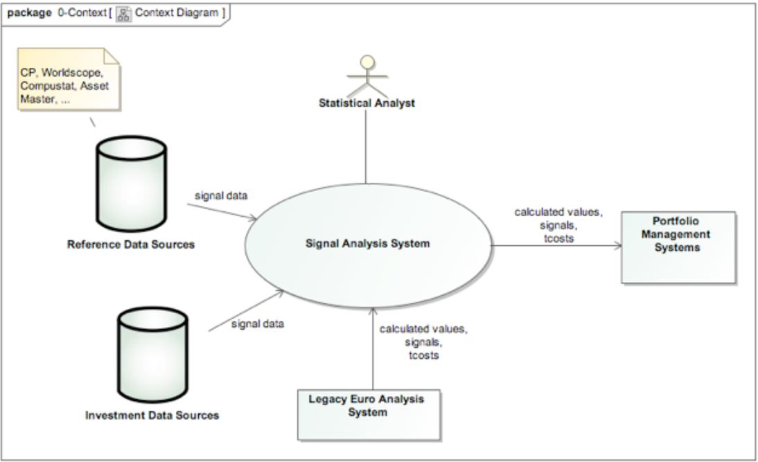
figure 1 - a context view
We could then continue by creating a Functional View that drilled inside the system and described the runtime components and connectors that it contains. This would be of interest to many stakeholders including development teams, technical writers, support staff and some parts of the end user community, as well as specialists like security assessors and auditors.
An example of a functional view is shown in Figure 2, as a UML component diagram. Again we won’t go into much detail here, but suffice to say that a functional view captures the structure of the system in-terms of functional elements (“components”), their responsibilities, interfaces and interactions, while abstracting away details about their implementation, deployment and so on.
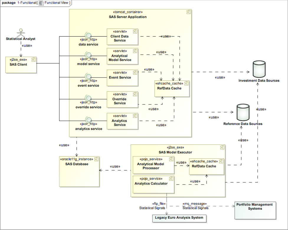
figure 2 - a functional view
Another view we might create for such a system could be a Deployment View that described the system’s deployment environment, showing the compute nodes that the software ran on, which parts of the system ran on which nodes, middleware that linked the system components together, database instances that were required, network requirements and so on. Such a view would be of interest to people supporting the system, the infrastructure teams, development teams and again specialists in areas like security, audit and compliance.
A possible Deployment View for the system outlined in our Functional View is shown in Figure 3, represented as a UML deployment diagram. As we’ll discuss later, base UML isn’t very strong at describing deployment environments and it is common to extend it or use alternative notations for the Deployment View. This model shows a basic deployment structure, illustrating the nodes that the system will run on, their connections, and the mapping of the system’s artefacts to each. We’ll see later how to put some more interesting information into this view.
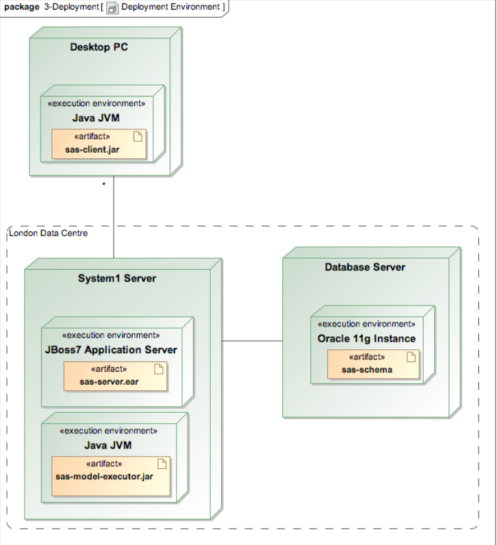
figure 3 - a deployment view
And so we could continue, adding views for different aspects of the architecture, dividing the problem up into manageable pieces and allowing people using the architectural description to focus on the parts that they care about.
So how would we decide which views to create and what we put in each of them?
Well firstly we should only create a view if it is of use to a stakeholder who cares about some aspect of the system. To put this succinctly, we should always “model with a purpose”, a principle identified a long time ago by one of my software development heroes, John Daniels [3]. In his original article John was talking about the different sorts of models available and when to use each, but the principle also applies when considering whether to create a model at all, as we are here. However we still don’t want to start from scratch every time. There have probably been many systems with similarities to ours already built and people have had to create views of them, so what did they do? We can answer this question by looking at sets of viewpoints that have been defined for us already.
A viewpoint is to a view, what a class is to an object. That is, it acts as a template and guide, to define the view’s purpose, what the view is useful for and what to put in that view. A formal definition of a viewpoint, from the same reference as before, is:
A viewpoint is a collection of patterns, templates, and conventions for constructing one type of view. It defines the stakeholders whose concerns are reflected in the viewpoint and the guidelines, principles, and template models for constructing its views.
A number of viewpoint sets have already been defined for various types of system and various domains, but the set we’ll use in this article is the set that Nick Rozanski and I created when we wrote our book [2]. on software architecture that I took the definitions above from. Our set of views is as follows:
- Context - describes the relationships, dependencies, and interactions between the system and its environment (the people, systems, and external entities with which it interacts). Includes the system’s runtime context and its scope and requirements.
- Functional - describes the system’s functional elements, their responsibilities, interfaces, and primary interactions; drives the shape of other system structures such as the information structure, concurrency structure, deployment structure, and so on.
- Information - describes the way that the architecture stores, manipulates, manages, and distributes information. This viewpoint develops a complete but high-level view of static data structure and information flow to answer the big questions around content, structure, ownership, latency, references, and data migration.i
- Concurrency - describes the concurrency structure of the system and maps functional elements to concurrency units to clearly identify the parts of the system that can execute concurrently and how this is coordinated and controlled.
- Development - describes the architecture that supports the software development process. Development views communicate the aspects of the architecture of interest to those stakeholders involved in building, testing, maintaining, and enhancing the system.
- Deployment - describes the environment into which the system will be deployed, and the dependencies the system has on its runtime environment. Deployment views capture the system’s hardware environment, technical environment requirements, and the mapping of the software to hardware elements.
- Operational - describes how the system will be operated, administered, and supported when it is running in its production environment, by identifying system-wide strategies for addressing operational concerns and identifying solutions that address these.
You can get a quick reference card that defines the essentials of each of these viewpoints from www.viewpoints-and-perspectives.info At this stage, I realise that alarm bells may be ringing, particularly if you work in an agile team where you use very little formal documentation. Have no fear, this is not a charter for waterfall style “big up-front design” documentation! A few misconceptions to clear up are as follows:
- Method vs Techniques – this isn’t a software development “method” where you have to start with the context view, then do the functional view, then do the information view and so on. This is a set of useful techniques and guidelines from which you need to choose what is valuable in your particular context. We have almost never created all seven views for a system and certainly not at the start of a project.
- Not Big Up-Front Design – this approach is also not meant to imply that the views are created before a line of code is written. You create the architectural views when there is demand for them. Some of that may be at the very start of a project before any code is written and some may be right at the end when the project is approaching production.
- Not Prescriptive – these views are a toolbox of options for you to consider when you need to develop an architecture. It is up to you when and if you need to use them.
- Not a Charter for Architectus Reloadus – another common misconception is that views are to be created by a single all knowing “Architectus Reloadus” character [4], and handed to the development team on tablets of stone. Nothing could be further from the truth. You may have one person take the lead on the architectural description or perhaps different individuals will take the lead on each part, or perhaps everyone will collaborate on everything. There is nothing in a view-based approach to limit or encourage one working style over another.
As I mentioned earlier, there are quite a few viewpoint sets around so if you can see value in the approach but think that these views are not right for you, read up on the other sets. Some of the ones worth knowing about are “4+1” [5], a set for embedded software from Siemens [6], the “Views and Beyond” set from the SEI [7], the Garland and Anthony set [8] and the set defined as part of RM-ODP [9].
Of course ultimately you can also create your own views to add to these sets or even define an entirely new set. That’s quite a lot of work though and these sets have been carefully thought out, documented and tested, so they are a good starting point.
A Palette of Views
Having introduced the idea of using views for architectural description, in this section we’ll delve a little more deeply into the content and usage of some of the more commonly used views.
Context View
The system we’ll use as an example is a simple statistics storage and processing system, used to receive statistics from one or more feeder systems, store the statistics, automatically calculate derived statistics and allow statistical analysts to interrogate the statistics and record deductions that they make from them. As such it is a classic small information system, with a central database, a user interface, some batch processing and some data loading. The system context is very simple and is shown in Figure 4.
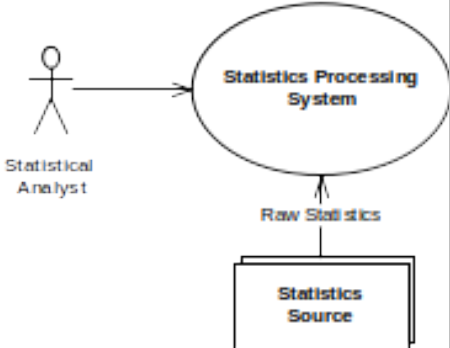
figure 4 - statistics system context
The key points to note about the system’s context are:
- The system accepts raw statistics data from one or more “source” systems.
- The system provides a user interface to the statistical analysts who are its only direct users.
Functional View
To understand more about how the system will work, we create a Functional View of the system. We’d follow the advice in the Functional Viewpoint in order to guide us through the process and this would tell us that this view contains a key model – the functional structure model. The full definition of the viewpoint provides advice on what a functional structure model contains and how to create and represent one, but for the purposes of our example, we’ll just consider the finished product, which is the UML component diagram in Figure 5 (and its supporting definitions).
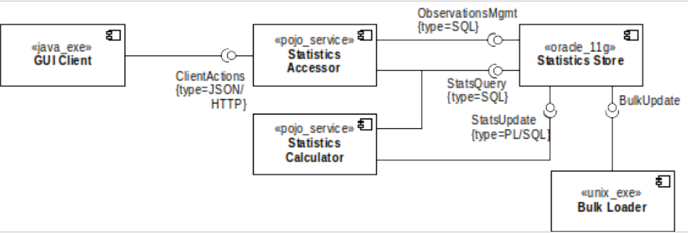
figure 5 - functional structure
Our functional structure model defines the set of runtime elements that the system contains, the responsibilities of each, the interfaces they provide and the interfaces they require (are dependent on).
- The GUI Client is a standalone Java client, which is responsible for providing the user interface to allow analysts to access the system. It requires the Statistics Accessor server’s ClientActions interface (which for a real system would need to be defined properly elsewhere). This interface is a web services interface as we used a UML tagged value to indicate that it is implemented as JSON over HTTP.
- The Statistics Store element is responsible for storing all of the system’s data and it offers three distinct interfaces, one to query statistics, one to update statistics and one to allow management of observations. We’ve used tagged values to indicate that these services are provided as SQL and PL/SQL (stored procedure) interfaces.
- The Statistics Calculator element is responsible for calculating the derived measures and so both reads and writes statistics via the StatsQuery and StatsUpdate interfaces.
- The Bulk Loader element is a binary executable (and so is tagged as a “unix_exe”) and for the purposes of this example, we can assume that it is some sort of utility like Oracle’s SQL*Loader. This element provides the interface from the external statistics sources.
As well as component descriptions and interface definitions, we would often add (or reference) a number of UML sequence diagrams here to illustrate how the elements interact for common system usage scenarios. We’ll omit these in the interests of space, given that the interactions in this system are fairly simple.
From the Functional View, we now know which application components will be present at runtime and how they depend on each other and interact in order to provide the functions of the system. What we don’t know yet is what data the system processes, how the components are packaged into processes or what sort of runtime environment the system is deployed into.
Information View
Some systems won’t need an Information View, but any system where the data is not all simply encapsulated inside the functional components is likely to benefit from one. An information view can contain a wide variety of models so it’s important to focus on the most important ones for the system at hand in order to stop the view becoming unwieldy.
For this system, we define the overall stored information structure and also the required lifecycle of the Deduction entity.
We have captured the information structure using the ERD in Figure 6.
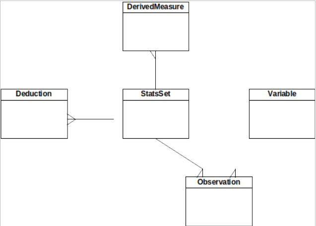
figure 6 - static information structure
While a real architectural data model would need to define the entities and relationships quite carefully, but in the interests of space we’ll just note the following key points:
- The system stores definitions of Variables it is monitoring.
- Observations exist for a variable, each observation is a value captured at a point in time.
- Statistics Set (StatsSet) collects a set of Observations that are related (presumably captured at the same time).
- Derived Measure is a derived statistic created by running a statistical calculation on the Statistics Set.
- A Deduction can be made manually from one or more Statistics Sets and related to them.
We can define valid entity lifecycles in a number of ways including entity life histories (ELHs) and UML state transition charts. We’ve used the ELH in Figure 7 to define the allowable set of states for the Deduction entity. We sometimes use ELHs in this way, in preference to state charts, as they’re simpler to read and so often more accepted by less technical stakeholders.
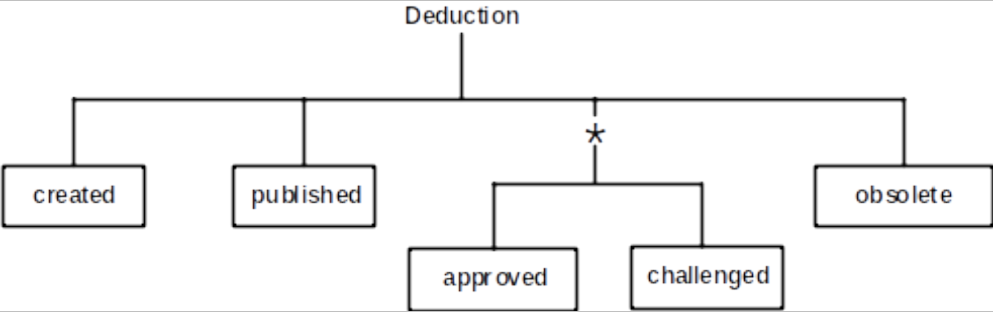
figure 7 - deduction lifecycle
The ELH for the Deduction defines the following points:
- A deduction is initially created.
- Then, a deduction has to be published before being visible to other users.
- The deduction can then repeatedly be approved or challenged by other users. It can only be in one state or the other (so challenging a deduction prevents it being approved).
- If the deduction is no longer relevant, it can be marked as obsolete (but note that it cannot be destroyed).
Having created an Information View, we now have a fairly clear idea as to the static information structure for the system along with some important constraints on it. We’d probably add further information to a real Information View such as data ownership (for example by using CRUD matrices), replication and latency models if relevant, expected data volumes for each significant entity and a data flow model if data flow between system elements was complicated.
Concurrency View
The Functional View (deliberately) doesn’t show how the functional elements are packaged up into OS processes or what OS threads exist at runtime. For simple systems, particularly those running within application servers, a Concurrency View often isn’t necessary as it’s fairly obvious from the functional structure. However, we’ve included one for our example system so that we can see what it might contain.
For our example system, we’ve developed a concurrency structure model, as suggested by the Concurrency Viewpoint. This uses a heavily stereotyped UML class diagram, in Figure 8, to show how the functional elements are packaged into processes and how they communicate using inter-process communication (IPC) mechanisms.
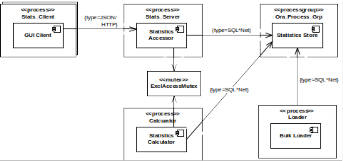
figure 8 - concurrency structure
- The GUI Client element is packaged into a Stats_Client process, many of which run concurrently (hence the multi-object notation).
- The Stats_Client processes all interact with a single Stats_Server process, containing the Statistics Accessor.
- The Statistics Calculator has been packaged into a Calculator process, which coordinates its access to the Statistics Store with the Stats_Server process using the ExclAccessMutex.
- The Statistics Store is packaged as a group of processes, Ora_Process_Group (the processes of an Oracle DBMS).
- The Bulk Loader runs as its own process, Loader.
- The Stats_Client communicates with the Stats_Server using JSON over HTTP, while the other processes communicate using Oracle SQL*Net.
Our example here is a little contrived and you could both simplify this concurrency approach and omit the Concurrency view for this particular system, but hopefully you can see that there are situations where such a view can be useful.
The Concurrency View doesn’t define how the processes are distributed across machines. This is deliberate as it focuses on the processes and the IPC mechanisms, which may allow for a number of different deployment approaches. We’ll see where the processes run in the Deployment view.
Development View
The Development View is where the architect can communicate any important architectural constraints that need to be respected when developing the system’s implementation. So this view is focused on design time concerns (rather than the runtime concerns that the Functional view is focused on).
Whether or not you need a Development View depends on the situation you find yourself in. If this is the early stages of the project where no serious implementation work has been started, then a Development View that captures the major decisions and constraints related to implementation will be a useful input for the development work. However once development is underway then the content of the Development View is probably better captured in a set of development standards on a wiki or some other accessible and maintainable place. You can always summarise the main points and reference them in your Development View if other stakeholders need to understand them.
The three common types of model used in this view are a (code) module structure model, models of common design features and a codeline model (i.e. how the code is organised, built, tested and released).
For our example, in the interests of space, we’ll just consider a module structure model, which we’ve captured as the UML component dependency diagram in Figure 9. This model is quite typical of the sort of module structure models that appear in Development views and it defines the design time code modules and their allowable interdependencies (in this case, organised as a set of layers).
The important points that this model is trying to communicate are as follows:
- The libraries in the system have been separated into three layers of abstraction: Application Support (AppSupport), Utility and Platform.
- The AppSupport modules can access all of the Utility modules and the Java 1.7 Library module in the Platform layer.
- The Utility modules can access all of the modules in the Platform layer.
Again due to the simplicity of the example, this module structure is a little contrived, but a clear definition of the intended inter-module dependencies is a valuable part of the architectural description to avoid tangles in the codeline.
The common design models are often captured as simple text and code snippets (e.g. how and where to use a logging library) or as system specific design patterns (e.g. the mechanism that all of the modules in the system must use to implement dynamic re-configurability).
Finally, the codeline model can be represented using UML, but when one is required, it is normally more effective to simply show the directory tree as a textual hierarchy and to explain how code is organised, built released and tested in some supporting text.
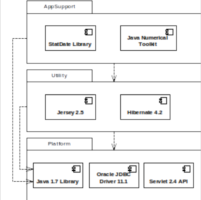
figure 9 - layer structure
Deployment View
The views we’ve seen so far have been describing the design of the system without any real reference to how it will run in its production environment; that’s where the Deployment View comes in. This view is concerned with the system’s runtime environment in terms of hardware, supporting software, network requirements and so on.
The number and types of models that you include in this view obviously depend on the complexity of the environment in question, but a “full” Deployment view would include a deployment model (i.e. processing and storage nodes, mapping of processes/elements to nodes and required interconnections), a network model (which highlights the network requirements between the nodes and suppresses the detail of what’s on the nodes) and a dependencies model (which captures the hardware and software that you need to be available on each node).
The deployment structure for our example system is described by the UML deployment diagram in Figure 10.
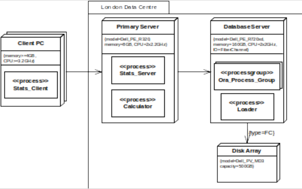
figure 10 - deployment structure
Frankly, UML isn’t all that strong at deployment models, just including a generic “node” and allowing them to contain artefacts and be linked together with associations. Therefore, deployment structure models often use simple “box-and-line” diagrams or “bend” the notation, as we have done here, and make use of stereotypes and tagged values to make the platform requirements clear. Our model in Figure 10 illustrates the following key points:
- The Stats_Client processes all run on Client PC nodes, with at least 4GB of memory and 3.2GHz processors.
- The Primary Server, Database Server and Disk Array nodes all run in the London Data Centre.
- The Primary Server hosts the Stats_Server and Calculator, running on a specific model of Dell server with the specified memory and CPU resources.
- The Database Server hosts the Ora_Process_Group and the Loader process, running on a specific server model, again with specified memory, CPU and specialised IO interface resources.
- The Disk Array is connected to the Database Server via a fibre channel interface (according to the tagged values) and is a specific model with specific capacity (but no specified disk layout, at least here).
We’re assuming certain standard network specifications between the machines and so we haven’t included a network model, but if this was complex or critical, we would create a network model to clearly communicate the connectivity we require.
The dependency model is normally captured using simple text and tables, such as the example for our system shown below.
                  Client PC:				Windows 8.1;
						Java JRE 1.7.0_02 or later;
						IE 10, Chrome 39 or later or Firefox 16 or later
Primary Server: 		Red Hat Linux 6 (corporate build);
						Java JDK 1.7.0_05 or later;
Database Server: 		RHEL 6 (standard database build);
						Oracle 11.2 Std Edition with .0.4 patchset;
						100GB buffer cache, auto sized SGA;
						auto storage management, 2 table spaces;
						OEM installed and working;
This dependency list captures the following key points:
- The Client PC nodes run Windows 8.1 and need a particular JRE and one of a set of tested browsers.
- The Primary Server node runs Red Hat Enterprise Linux based on a standard corporate build, along with fairly specific JDK version.
- The Database Server runs RHEL as well, but a different build and Oracle 11.2 is needed with a very specific patch set and some basic configuration assumptions that the development team will assume.
- The level of detail that a dependencies list needs to capture varies according to the standardisation of the environment that you’re working in, but it’s often useful to err on the side of caution and provide plenty of detail so that any erroneous assumptions can be spotted as early as possible.
Operational View
While the Deployment view has defined the technical structure that we’ll use to host our system, it hasn’t defined how we’re going to get the system running in that environment, migrate our workload to it and keep it running when in production. The Operational View addresses these concerns.
An Operational view contains a number of models that define aspects of the operational environment such as:
- The approach to be used for operational configuration (i.e. how the configuration of the application and underlying system software will be managed in terms of configuration sets, how the sets get applied, how inter-dependencies are managed and so on).
- How the system will be monitored and controlled, in terms of the technologies to be used any extension or configuration that they will required and any specialist tools that will be provided along with the system.
- The operational requirements of the system (i.e. what you’ll be expecting the system administrators to do on a routine basis).
- What strategies will be used to install the system, migrate data and workload to it and back it out of production if needed, should things go seriously wrong during migration.
We’re not going to try to capture the Operational view for our system here because it would be a large “text and tables” view that would need a lot of space to present (and like the Development view, it can often make sense to put this in a separate document rather than the main architectural description). However, hopefully you can imagine what sort of content this view would normally contain.
How Much is Enough?
As we discussed earlier, a perennial challenge for the software architect is how much architectural documentation to produce. Using a view-based approach helps to focus attention on the important parts of the problem and constantly challenges you to justify each view that you produce, but it’s still difficult to know when you have enough.
Some of the major questions we need to answer are which views are needed? How much effort should go into each? And how much formality is required in their production and presentation? A sketch on the whiteboard for each, or a UML model with supporting information in a document?
Over the years, I’ve developed a simple set of principles to help me answer these questions for my projects.
- Capture What They Care About – as already mentioned, make sure you have a customer for everything you document. That customer might be you (in which case you have total freedom as to how you do it) but in most cases, you’ll want to have someone else interested. So document what the consumer wants to know in a way that they will understand. (More technical stakeholders may well value quite formal and detailed documentation, less technical stakeholders probably want more abstract and informal representations).
- More Change Implies Less Documentation – while this is counter intuitive to some people I’ve found that the more you expect things to change, the less effort and formality you should put into architectural documentation. Otherwise, you get stuck in an endless loop of updating documentation and it is always out of date.
- Document the Stable Essentials – similarly, when you do decide what to document, find the key stable structures in your system and explain them clearly. This document can be long lived and valuable (provided that you have someone interested in reading it).
- Listen to Your Stakeholders – if you know who your stakeholders are and get to understand them, then the set of architectural documentation that you need to produce is much clearer.
- Remember the Stakeholders Who Need Formality – when considering the stakeholders closest to you (like end users, development teams and so on) it is often easy to conclude that pretty informal and lightweight documentation will be fine. After all these groups should be constantly communicating with each other. However stop and consider the other stakeholders who you see less often. Groups like infrastructure providers, compliance officers, and auditors often need (or may demand) much more formal architectural documentation.
- Consider the Documentation as Data – when considering how formal to make your architectural description, consider what you could do with it if you could treat it as data. I’ve discussed this elsewhere [10]. but briefly, remember that if you can represent your documentation in a machine readable form (a UML model in a good tool, a spreadsheet of data, a semantic wiki Error: Reference source not found) then you can use it for other things – like answering questions about your architecture – which opens up many possibilities and may make capturing it in a fairly formal way worthwhile.
The overarching principle behind all of these principles is, as we mentioned earlier, to model with a purpose. I have always found that if you think through who would be interested in the architecture documentation, what they will use it for and what they will understand, the level of documentation required becomes much clearer (and much easier to justify producing).
An analogy which I find helpful is that of a shopping list for groceries. If you’re going shopping for the ingredients for dinner, you’re not going to describe this in JSON or XML even if you type it into a computer. However if your shopping list is for the catering service for an airline then you will need it in a machine-readable form to allow automated processing. Similarly for an architectural description, be as formal as you need to be for the uses that you’ll put the architectural description to.
My experience suggests that the relationship between the effort you put into an architectural description and the value you can get back from that is characterised by the shape of the graph in Figure 11.
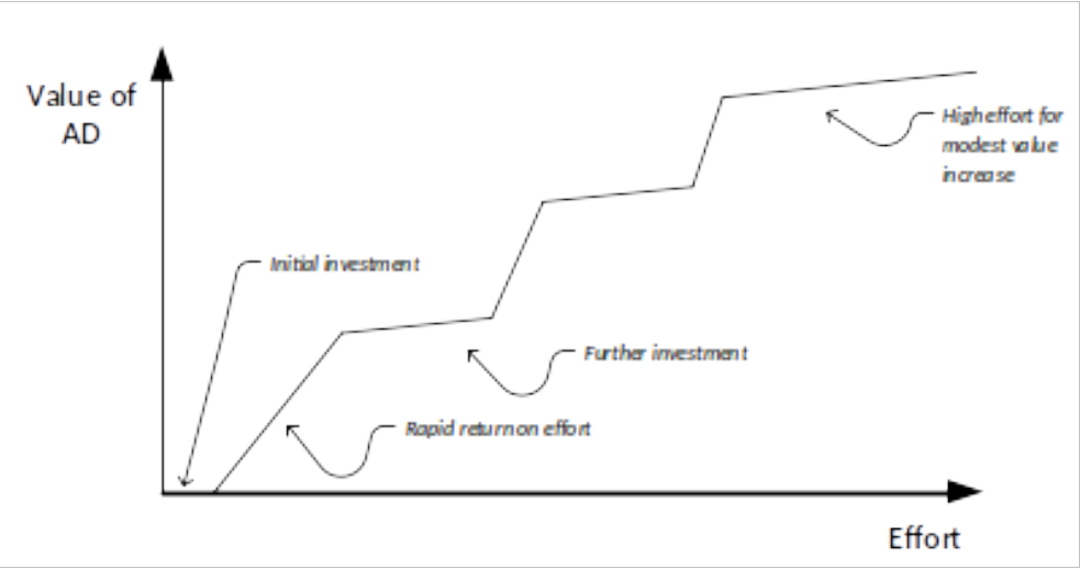
figure 11 - effort value relationship
Early on, you need to put some initial effort into the process to get any value from the AD, but relatively modest investments in architectural description produce value quite quickly. Then some more effort is needed to increase the value of the architectural description (probably increasing its scope or sophistication) and once this is achieved, then again you can gain quite a lot of value for a modest increase in cost. However then at the end, it takes a lot of effort to produce relatively marginal improvements in the value that it is possible to extract from the activity. Make sure you know where you are on your effort/value graph so that you know when to invest effort and when not to.
Summary
Describing the architecture of software intensive systems is a difficult task because complex systems have many related dimensions that need to be explained and a wide variety of stakeholders who want to understand some subset of the overall architecture. In this article we have explored two important dimensions of this problem.
In order to describe the complex structures of a system we have introduced architectural views as a simple, proven and practical approach, which breaks the problem down into manageable pieces, or views, each one describing a distinct aspect of the architecture. Sets of viewpoints to guide this process are already available and can provide you with a useful starting point to design the set of views needed for your own systems. The approach has been around long enough to prove its usefulness and in fact there is even an ISO standard for view based architectural description [1].
However even when using a view-based approach we need to decide how much effort and formality is worth investing in each view that we find we need. To help us think this through for a project, we’ve identified some simple principles that focus our effort on who will be using each view, what they want to use it for and how the architectural description might be put to use.
When we understand these two dimensions of the architectural description problem, then we can focus on what really matters - designing and describing an architecture that meets the needs of our stakeholders!
References
- ISO/IEC 42010:2007, Systems and Software Engineering -- Recommended Practice for Architectural Description of Software-Intensive Systems, 2008
- Software Systems Architecture: Working with Stakeholders using Viewpoints and Perspectives, Nick Rozanski and Eoin Woods, Addison Wesley 2011. Supporting web site at www.viewpoints-and-perspectives.info.
- Modelling with a Sense of Purpose, John Daniels, IEEE Software, January/February 2002.
- Who Needs an Architect?, Martin Fowler, IEEE Software, September/October 2003.
- Architectural Blueprints — The “4+1” View Model of Software Architecture, Philippe Kruchten, IEEE Software, November/December 1995.
- Applied Software Architecture, Christine Hofmeister, Robert Nord and Dilip Soni, Addison Wesley, 2000.
- Documenting Software Architectures: Views and Beyond, Paul Clements et all, 2nd Edition, Addison Wesley, 2010.
- Large-Scale Software Architecture: A Practical Guide Using UML, Jeff Garland and Richard Anthony, Wiley, 2002.
- Reference Model of Open Distributed Processing (RM-ODP), technical report 10746, International Organization for Standardization, 1994.
- Harnessing UML for Architectural Description--the Context View, Eoin Woods, IEEE Software, November/December 2014.
- Experiences with Semantic Wikis for Architectural Knowledge Management, Remco de Boer and Hans van Vliet, 9th Working IEEE/IFIP Conference on Software Architecture (WICSA), 2011, see: IEEE Explore